REPRESENTATIVE STUDY · Electronics · Energy
Keeping a sealed power-electronics enclosure within its temperature limits
A conjugate heat-transfer study that finds the hot spots in a sealed inverter enclosure and tests whether the cooling design has margin on a hot day.
A sealed enclosure protects power electronics from dust and moisture, and traps their heat. The question is whether every component stays below its limit at the highest ambient temperature the product will see.
The question
The enclosure holds several heat-dissipating devices on heat sinks, a circulation fan and a finned outer wall. The design team needs peak component temperatures at worst-case ambient, the margin to each limit, and a comparison of options if the margin is too thin: a second fan, a taller heat sink or a different layout.
The approach
Prescribing a heat-transfer coefficient on each surface would mean assuming the answer. Instead, air and solids are solved together with conjugate heat transfer, so the temperature of each heat sink and the air passing over it are consistent with one another. Downstream components sit in the thermal wake of upstream ones, which is exactly the effect a hand calculation misses.

Radiation between internal surfaces and the enclosure wall is included, because in a sealed box with modest air speeds it carries a meaningful share of the heat. A fan-failure case is run with natural convection alone to show how long the design can tolerate it. See our guide to conjugate heat transfer for electronics cooling.
What the study delivers
- A table of component temperatures against their limits for each operating case
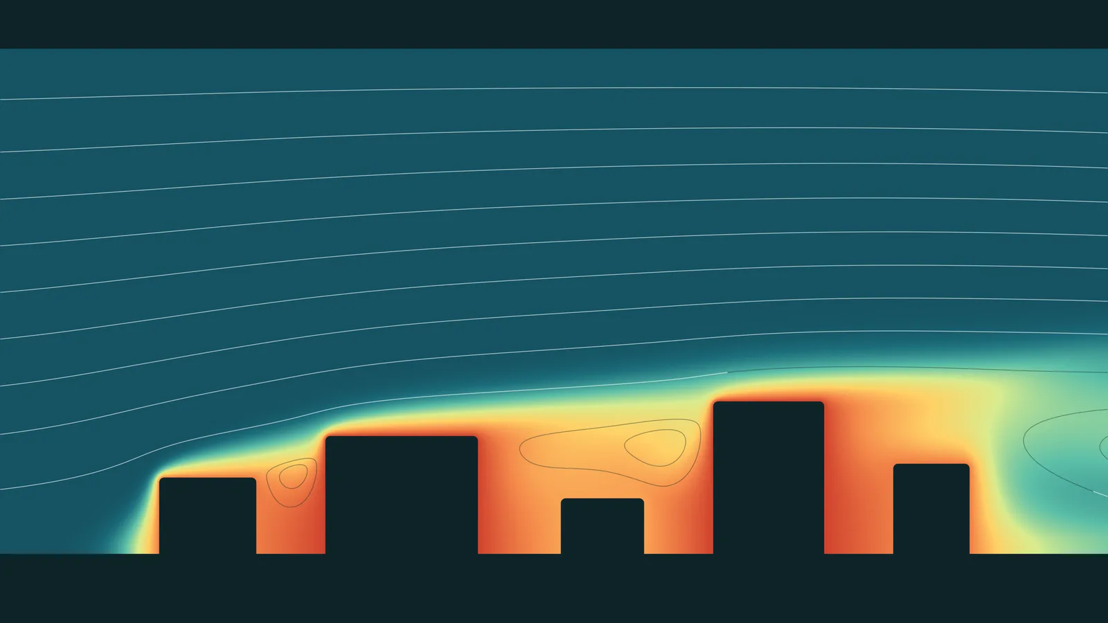
- Temperature maps on boards and heat sinks that locate the hot spots
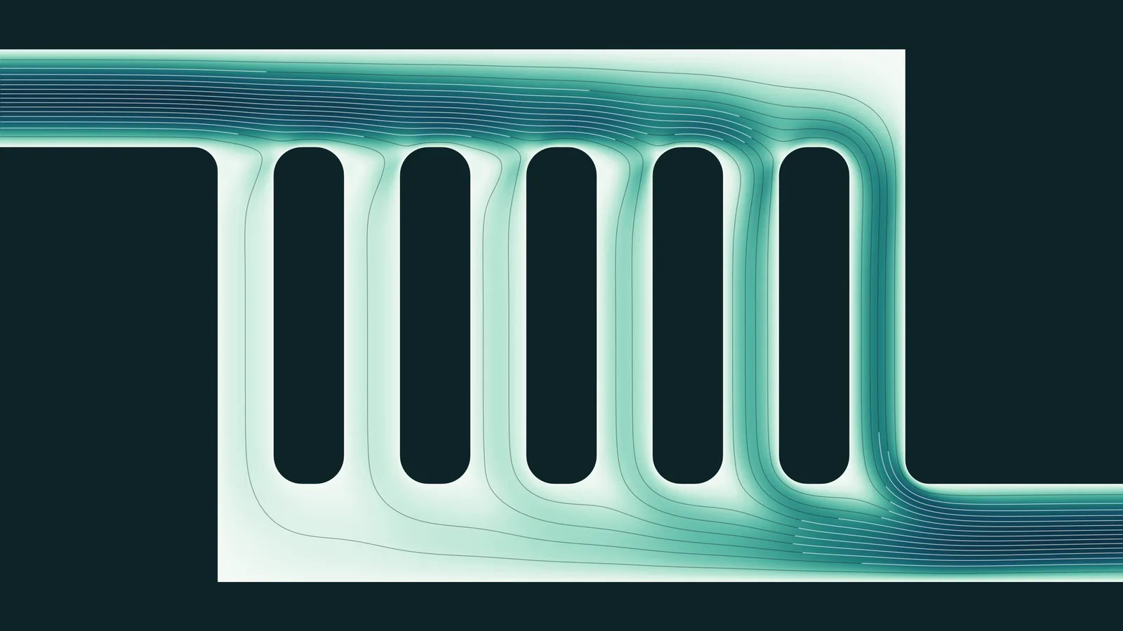
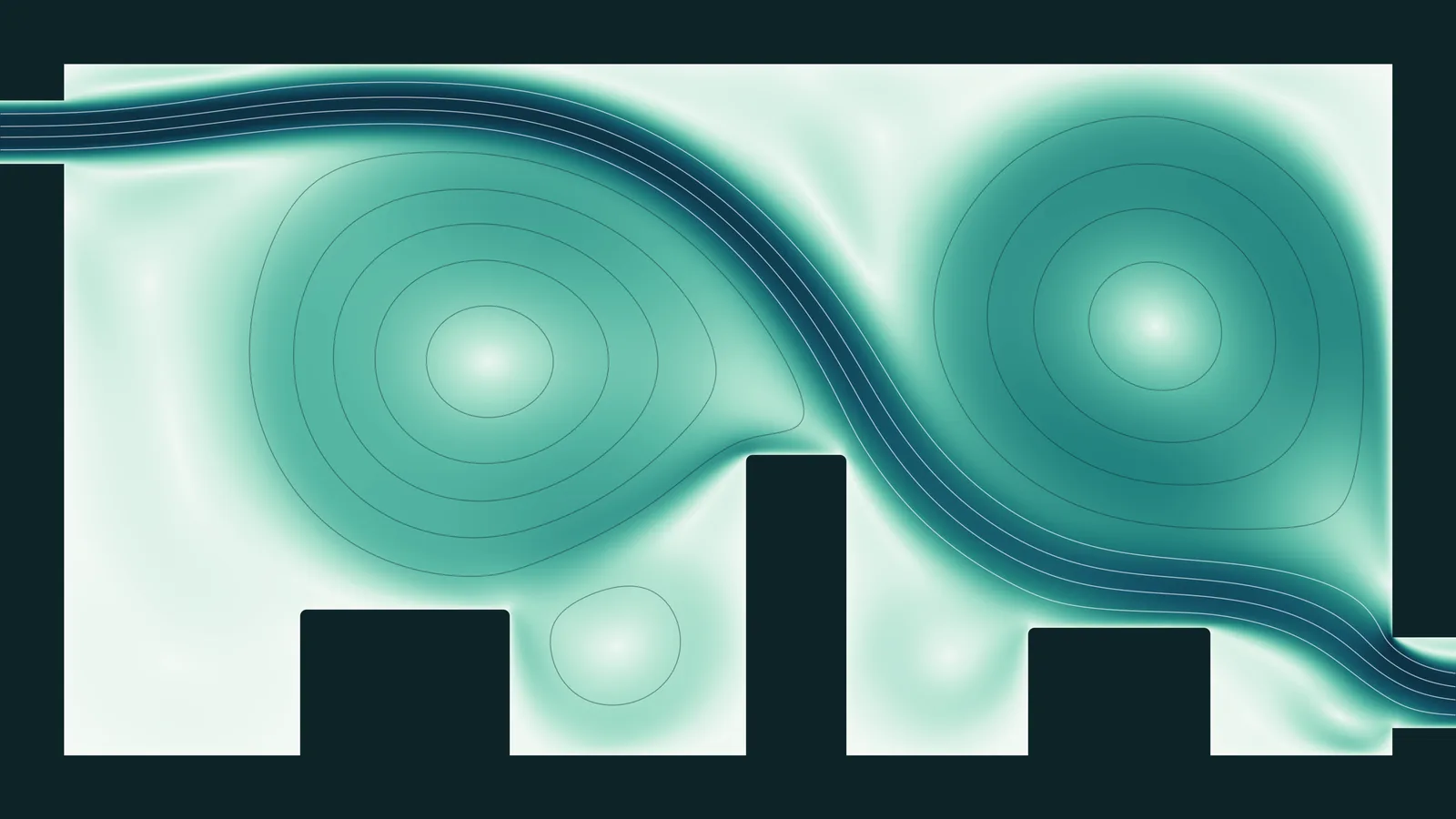
- The air path inside the enclosure, showing recirculation and poorly ventilated corners
- A like-for-like comparison of the cooling options
Why it matters
Thermal problems found on a prototype cost a board respin or a mechanical redesign. Found in simulation, they cost a change to a CAD model. The study also shows where margin is being wasted, which is often as valuable as finding where it is missing.
About this study. This is a representative example of how we approach this type of problem, shown with computed illustrative imagery. It is not a report on a specific client engagement.