REPRESENTATIVE STUDY · HVAC
Testing ventilation effectiveness in a controlled room
Modelling supply, extract, heat loads and buoyancy to check that clean air reaches the critical zone before the ductwork is installed.

An air-change rate on a drawing says how much air enters a room, not where it goes. In a laboratory, cleanroom or equipment room, where the air goes is the whole point.
The question
A room with heat-generating equipment needs its critical zone kept within a temperature band and swept with fresh air. The designers have a supply and extract layout and want to know, before installation, whether supply air actually reaches the zone, whether stagnant pockets form behind equipment, and how the pattern changes between summer and winter supply temperatures.
The approach
The room is modelled with its furniture, equipment and heat loads. Buoyancy is included, since a cool supply jet falls and warm plumes rise, and the two together decide the flow pattern. The supply diffusers are represented by their throw and spread rather than as plain openings.
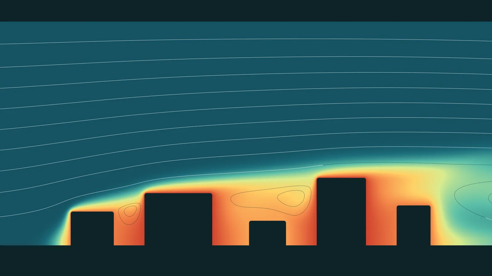
Alongside velocity and temperature, the study computes the local mean age of air: how long, on average, air at each point has been in the room. It turns a hard-to-read flow field into a single map of well-ventilated and poorly ventilated regions.
What the study delivers
- Velocity and temperature fields on planes through the occupied and critical zones
- Age-of-air maps that expose short-circuiting from supply to extract and stagnant corners
- Air speed and temperature against comfort or process limits
- A comparison of alternative diffuser and extract positions
Why it matters
Moving a diffuser on a drawing costs nothing. Moving it after commissioning means opening ceilings. The study checks the air path while changes are still cheap, and gives the commissioning team a picture of what they should expect to measure.
About this study. This is a representative example of how we approach this type of problem, shown with computed illustrative imagery. It is not a report on a specific client engagement.